Foshan nanhai qili electronics co. LTD
Dedicated to high quality electronics and spare
parts production service providers
|
|
HOTLINE: 0757-85656013 |


Working principle and driving circuit of relay
Author:佛山市南海启力电子有限公司
Click:
Time:2019-09-06 11:42:42
Relay is an electronic control device, it has a control system (also known as the input loop) and the controlled system (also known as the output loop), usually used in automatic control circuit, it is actually a small current to control a large current of an "automatic switch".Therefore in the circuit plays the role of automatic regulation, safety protection, conversion circuit and so on.
Relay characteristics of relay
The input signal x of the relay increases continuously from zero to the action value xx when the armature begins to close, and the output signal of the relay immediately jumps from y=0 to y=ym, that is, the normally open contact changes from broken to on.Once the contact is closed and the input x continues to increase, the output y will no longer change.When the input x drops from a value greater than xx to xf, the relay starts to release and the normally open contact is disconnected.We call this characteristic of the relay relay characteristics, also known as the relay input-output characteristics.

The working principle and characteristics of relay
Working principle and driving circuit of relay
Principle and characteristics of electromagnetic relay
Electromagnetic relays are generally composed of iron core, coil, armature and contact reed.As long as a certain voltage is added on both ends of the coil, a certain current will flow through the coil, thus generating an electromagnetic effect. The armature will overcome the tension of the return spring and attract to the core under the action of electromagnetic force, thus driving the moving contact of the armature to attract the static contact (normally open contact).When the coil is cut off, the electromagnetic attraction will disappear, and the armature will return to its original position in the spring's reaction force, so that the moving contact and the original static contact (normally closed contact) will be released.
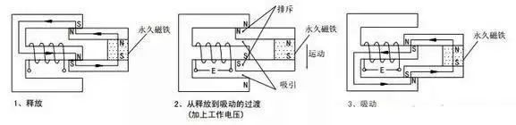
After the permanent magnet maintains the release state and the working voltage is added, the electromagnetic induction causes the armature and the permanent magnet to produce the attraction and repulsion moment, and produce the downward movement, finally reaching the suction state.
Transistor drive drive circuit
Working principle and driving circuit of relay

NPN triode is recommended when transistors are used to drive relays.Specific circuit is as follows:
When the input is high, the transistor T1 is saturated, the relay coil is energized, and the contact is closed
When the input power is low, the transistor T1 cut-off, relay coil power off, contact disconnect
Functions of components in the circuit:
Transistor T1 is the control switch
Resistance R1 mainly ACTS as current limiting and reduces the power consumption of transistor T1
Resistance R2 makes transistor T1 reliably cut off
The diode D1 reverse continuation provides a discharge path in the relay coil when the triode is turned off from conduction and its voltage is clamped on +12V
Integrated circuit driver circuit
Working principle and driving circuit of relay

Integrated circuits with multiple drive transistors have been used to simplify the design of boards that drive multiple relays.
When the input end of 2003 is high, the corresponding output outlet outputs a low level. Both ends of the relay coil are energized, and the relay contact is sucked.When the input end of 2003 is at low current, the corresponding output outlet is in a high resistance state, the relay coil both ends are power off, and the relay contact is disconnected.
Working principle and driving circuit of relay
Drive circuit of 24V relay
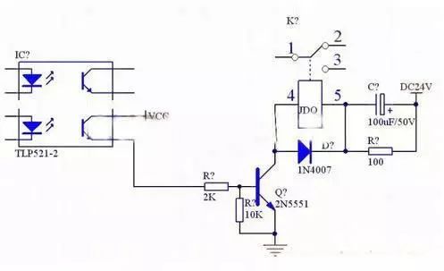
Relay series RC circuit: this form is mainly used in circuits where the rated operating voltage of the relay is lower than the supply voltage.When the circuit is closed, electromotive force will be generated in the relay coil due to the self-induction phenomenon to prevent the increase of the current in the coil, thus extending the time of absorption, and the time of absorption can be shortened after the RC circuit is connected in series.
The principle is that at the moment when the circuit closes, the voltage at both ends of capacitor C cannot be suddenly changed, which can be regarded as a short circuit. In this way, the supply voltage higher than the rated working voltage of the relay coil is added to the coil, thus speeding up the increase of the current in the coil and making the relay absorb rapidly.When the power supply is stable, capacitor C does not work and resistor R ACTS as a current limiter.
Selection of rated operating voltage of relay
Rated working voltage of relay is the most important technical parameter of relay.When using the relay, the working voltage of the circuit (that is, the circuit where the relay coil is) should be considered first. The rated working voltage of the relay should be equal to the working voltage of the circuit.
Generally, the operating voltage of the circuit is 0.86 of the rated operating voltage of the relay.Note that the voltage of the workpiece in the circuit must not exceed the rated operating voltage of the relay, otherwise the relay coil is easy to burn out.
In addition, some integrated circuits, such as NE555 circuit, can directly drive the work of the relay, while some integrated circuits, such as COMS circuit output current is small, need to add a transistor amplifier circuit to drive the relay, which should consider that the transistor output current should be greater than the rated operating current of the relay.
Transistor drive circuit
When a transistor is used to drive a relay, the emitter of the transistor must be grounded.Specific circuit is as follows:
Working principle and driving circuit of relay

Introduction of the principle
When the NPN transistor is driven: when the transistor T1 base is input with high power, the transistor saturates and turns on, and the collector becomes low level. Therefore, the relay coil is energized and the contact RL1 is sucked up.When the transistor T1 base is input with low power, the transistor is cut off, the relay coil is cut off, and the contact RL1 is disconnected.
 Contact us

Foshan nanhai qili electronics co. LTD Registration no. : ICP 0000000号
Phone:0757-85656013 Fax:0757-85601063
URL:gdkili.com
Address: no. 4, gangmeisha industrial zone, zhoucun, lishui town, nanhai district, foshan city, guangdong province

Official qr code
Copyright @ VillaGrandis All Rights Reserved ICP备案号180006020号-3