
Foshan nanhai qili electronics co. LTD
Dedicated to high quality electronics and spare
parts production service providers
|
|
HOTLINE: 0757-85656013 |


Principle and notice of relay drive circuit
Author:佛山市南海启力电子有限公司
Click:
Time:2019-09-06 11:46:16
The drive current of relay generally needs 20-40ma or more, and the coil resistance is 100-200 ohms, so the drive circuit should be added.
1. Transistor driven relay
The emitter of the transistor must be grounded. The specific circuit is as follows:

When the NPN transistor is driven: when the transistor T1 base is input with high power, the transistor saturates and turns on, and the collector becomes low level. Therefore, the relay coil is energized and the contact RL1 is sucked up.
When the transistor T1 base is input with low power, the transistor is cut off, the relay coil is cut off, and the contact RL1 is disconnected.
PNP transistor drive circuits are not currently in use and will not be introduced here.
1.1 functions of components in the circuit:
Transistor T1 can be regarded as a control switch. VCBO≈VCEO≥24V is generally selected, and the magnification factor is generally selected between 120 and 240.Plays a role of current limiting resistor R1 is mainly, reduce the power consumption of the transistor T1, and resistance to 2 K Ω.Resistance R2 make T1 as reliable transistor, Ω resistance value is 5.1 K.Diode D1 reverse continuation, inhibit the surge, generally choose 1N4148 can.
Integrated circuit 2003 drive relay
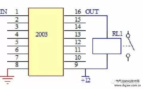
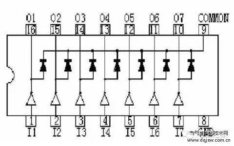
Figure 1 ~ 7 is the signal input (IN), 10 ~ 16 is the output signal (OUT), 8 and 9 is the integrated circuit power supply.The diagram on the right shows the block internals.
2.1 introduction to working principle
According to the input and output characteristics of integrated circuit driver 2003, someone referred to it as "driver", "invertor", "amplifier" and so on, now commonly used model is: TD62003AP.When the input end of 2003 is high, the corresponding output outlet outputs a low level, the relay coil is energized, and the relay contact is closed.When the input end of 2003 is at low current, the relay coil is cut off and the relay contact is disconnected.In 2003, we have integrated diodes with reverse continuation function, so we can drive the relay directly.
2.2 maintenance
The method to judge the quality of 2003 is very simple. The input and output voltages are measured respectively with the dc level of the multimeter. If the input terminal 1 ~ 7 is low level (0V), the output terminal 10 ~ 16 must be high level (12V).Conversely, if the input terminal 1-7 is high level (5V), the output terminal 10-16 must be low level (0V).Otherwise, the drive is broken.
Test conditions: 1. Standby; 2.2. The boot.
Test method: adjust the multimeter to 20V dc, connect the negative pen to the ground wire of the electronic control plate (7812 pressure stabilizer heat sink), and touch each foot of the positive pen respectively in 2003.
 Contact us

Foshan nanhai qili electronics co. LTD Registration no. : ICP 0000000号
Phone:0757-85656013 Fax:0757-85601063
URL:gdkili.com
Address: no. 4, gangmeisha industrial zone, zhoucun, lishui town, nanhai district, foshan city, guangdong province

Official qr code
Copyright @ VillaGrandis All Rights Reserved ICP备案号180006020号-3
